Serial Bridge Using ESP8266
One of the most well-known (appeared on Hackaday’s blog) and well-designed projects to make ESP8266 as a WiFi-UART bridge is jeelabs’s esp-link. Actually, this project is far beyond being a simple serial bridge as it also manages MQTT client pub/sub and REST HTTP requests in order to connect the MCU to the internet. Moreover, it can be used to flash the attached MCU. Esp-link has a very handy web interface stored inside the ESP.

To make the test, we will use ESP8266 development board, specifically NodeMCU.
Prepare The Software
First, we need to download one of the release images of the project from releases page. The compressed file (A .tgz file is beside the download word in bold) should have 5 bin files :blank.bin, boot_v1.x.bin, esp_init_data_default.bin, user1.bin and user2.bin. The ESP8266 board should be connect after downloading one of the available download tools like: Flash download tool from Espressif or Nodemcu flasher.Now, follow the flashing guidelines available in Readme file according to your ESP8266 edition and set the bin files addresses according to your module memory size.


You can simply make the Flash download tool from Espressif find it for you by connecting it and pressing “start” to get the required specification from the boot message.


Alternatively, you can read the boot message using a serial console with 76600 baud.


After flashing the image files successfully, you should see a new WiFi network.


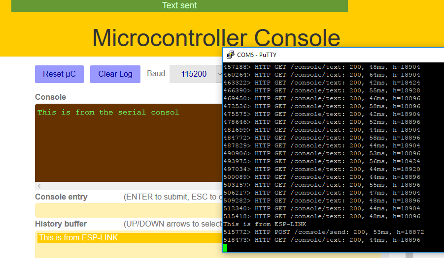
Connect to it and type this IP address into the browser http://192.168.4.1 . Now, you should see the home page.
Prepare The Hardware
To test the serial bridge code, we will achieve the following connection: TX0 from ESP with RX of the device and RX0 with TX of the device that sends serial information and needed to be bridged via WiFi. For the sake of the test, the device here would be a USB-TTL cable (USB-UART converter) and the data will be sent and received from a console (PUTTY for instance).

Now, let’s see some serial data fly over the air!


Finally, I think a considered amount of time is needed to explore the other options of this amazing project!
Serial Bridge Using ESP8266 (Simpler)
The previous project could be too complicated to do the simple job of converting Serial connection to a WiFi connection. So I decided to port a project described in the rest of this article written in Arduino. The ported code works on ESP8266 and can be download from here:

The explanation in the next section should be followed to know who to use it but with ESP8266, where simply by using a specific IP/Port via a Tellnet connection, the Serial data can be reached out.
Serial Bridge Using ESP32
A project via Github presents a WiFi to Serial bridge for the 3 UART ports available in ESP32. This project is written using Arduino IDE and supports ESP32 as an access point (AP) that broadcasts a specific WiFi network with predefined SSID and password in the code or a station. However, every UART port on ESP32 is accessible after making a WiFi connection with ESP32 via a specific IP and port.Let’s prepare the needed software and hardware to test this project.
Prepare The Software
As the project uses Arduino SDK with ESP32 core, then we need to add Arduino core for the ESP32 to the Arduino environment. The official documentation of ESP32 core from Espressif has an installation guide, but the easiest way to add this core is to download the repo as a zip file then decompress it in the following directory: (Windows) \Documents\Arduino\hardware\espressif\esp32 (Linux) folder is named “Sketchbook” and it is typically located in /home/The next step is to get the compilation tool-chain xtensa-esp32-elf by executing one of the get.exe or get.py files available in the tools folder according to your machine type.
To test this all together, open the Arduino IDE and check the Tools>boards menu


Now, testing the compilation of a simple program is needed also. The following test code can be used.
#define PIN_LED 1 // built_in
void setup()
{
pinMode(PIN_LED, OUTPUT);
}
void loop()
{
digitalWrite(PIN_LED, HIGH);
delay(1000);
digitalWrite(PIN_LED, LOW);
delay(1000);
}
Prepare The Hardware
ESP32 has many different development boards. The one used here is Goouuu-ESP32 Development Board

And has the following pinout:
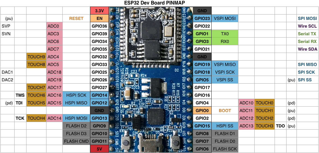

Image Source: Espressif Github Repo
To test the serial bridge code, we will do the following connection: TX0 from ESP with RX of the device and RX0 with TX of the device that sends the serial information and needed to be bridged via WiFi. For the sake of the test, the device here would be a USB-TTL cable (USB-UART converter) and data will be sent and received from a console (PUTTY for instance).


Now download the Arduino code from Github and upload it to ESP32. Choose from Tools>boards>ESP Dev Module. Many things can be configured before uploading the code to ESP32 like choosing the working mode as a station or an access point and many other things.
#define MODE_AP // phone connects directly to ESP

//#define MODE_STA // ESP connects to WiFi router
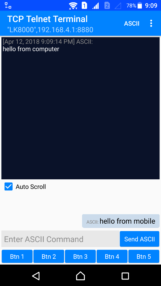
If no changes are done, the bridge will broadcast a WiFi network with SSID “LK8000” and password “Flightcomputer”. Connect to the WiFi network and open the Putty program then use the following setups: one for the Serial connection for the USB-UART converter.


And another to connect to the WiFi server using one of the following IP/Port according to the used UART port.
- 192.168.4.1:8880 for UART0
- 192.168.4.1:8881 for UART1
- 192.168.4.1:8882 for UART2


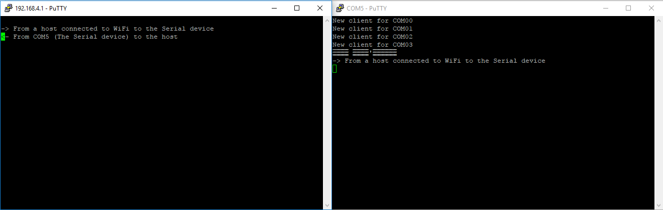
Now, open the two consoles and try the magic!


Do you need to know more about ESP32? Read this series “All About ESP32”.