The title itself “Given Hardware Behavioral Testing Is Needed, Then Use Analog Discovery 2 With Behave Python Framework” is written in Gherkin language which is designed to be non-technical and human-readable, and collectively description language for use cases related to a software system. Testing is a key step during development or production. The more you have clear test plans that cover all features, the more you discover bugs in an early stage.
Some may use testing as a technique during agile software development called Behavior-driven development (or BDD) which facilitates collaboration between technical and non-technical participants in software development, and this in a wider scope can include hardware and firmware development.


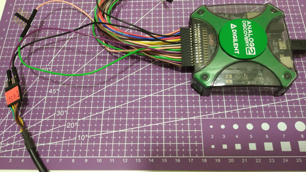
Many embedded systems teams, designing the testing platform for their product/s, where the testing platform itself is a standalone project in terms of development. The testing platform comes usually in the shape of a Jig that has Pogo pins (spring-loaded pin) to make electrical connections with some testing points on the product PCB.
This includes designing a circuit capable to do ADC, DAC, and digital reading. Moreover, testing platform should be able to show testing results, either in a simple form, simply a green LED (pass) or red LED (fail), or to report more detailed information to a connected PC, USB connection mostly. This will include in a way or another designing simple communication protocol between the PC and the testing platform and maybe a small driver code on the Host PC.
When I did a review for Digilent’s USB multi-purpose instrument Analog Discovery 2, and found that all its rich features can be accessed using the provided SDK APIs, one of the first things I had in mind is to try integration between AD2’s SDK and Behave Python Framework. Behave uses tests written in a natural language style and implement them in the background in Python code.
  Scenario Outline: Static I/O
     Given Analog Discovery 2 is connected
      When Output #<output_number> set to <output_state>
      Then Input #<input_number> is <input_state>
      Then Close connection with Analog Discovery 2
    Examples:
        |  output_number  |  input_number | output_state | input_state |
        |  0              |  1            |  1           | 1           |
        |  0              |  1            |  0           | 0           |
That was an example of one test written using Gherkin language and we will see how it will be implemented using Behave framework and Analog discovery 2 SDK.
Rather than spending time on designing a board to do the required for testing the hardware, Digilent provided access to all Analog discovery 2 features, including the 30+ MHz Oscilloscope, 12 MHz Wave generator, 16 channel Logic Analyzer, 16 Static I/O and more. For me, as a developer, I can’t find a fancier and more straight forward platform to conduct the Hardware test plans than using Behave and Analog Discovery 2.
Read more about Analog Discovery 2:
- The Multi-function Instrument “Analog Discovery 2” Review
- ‘Given’ Hardware Behavioral Testing Is Needed ‘Then’ Use Analog Discovery 2 With Behave Python Framework
- Use AD2 to Check FT2232H Outputs
Waveform is the PC program that interacts and controls Analog Discovery 2 and it comes with an SDK inside. SDK files can be found in the same directory where Waveform is installed. A reference manual is available for all APIs besides samples code written in C and Python, covering almost all features.
Let’s start now the practical work by defining the following feature file which consists of 2 scenarios. First, is to control an output and sense the change from another input. Two I/O pins from Analog Discovery 2 are connected. Second, to connect a UART transmitter and expect to receive certain value using Analog Discovery 2 logic Analyzer. Let’s create a directory with a file called basics.feature that contains the following:
Feature: Check Baiscs

  Scenario Outline: Static I/O
     Given Analog Discovery 2 is connected
      When Output #<output_number> set to <output_state>
      Then Input #<input_number> is <input_state>
      Then Close connection with Analog Discovery 2
    Examples:
        |  output_number  |  input_number | output_state | input_state |
        |  0              |  1            |  1           | 1           |
        |  0              |  1            |  0           | 0           |

  Scenario Outline: UART
     Given Analog Discovery 2 UART is configured
      Then Wait to send 0x<rx_char> via UART
      Then Close connection with Analog Discovery 2
    Examples:
        |  rx_char  |
        |  AA       |
        |  55       |

Inside the same directory, create a subdirectory called steps, and inside it create basics.py to implement each sentence found in the feature file.
Here is how ‘Given Analog Discovery 2 is connected’ is implemented inside basics.py:
@given('Analog Discovery 2 is connected')
def step_impl(context):
    dwf.FDwfDeviceOpen(c_int(-1), byref(hdwf))
    assert hdwf.value != hdwfNone.value,"Check USB connection with AD2"
and ‘When Output #<output_number> set to <output_state>’ looks like:
@when('Output #{output_number} set to {output_state}')
def step_impl(context,output_number,output_state):
    # enable output/mask on 8 LSB IO pins, from DIO 0 to 7
    IO_enable_mask = 0x0000 | (1 << int(output_number))
    IO_state_mask = 0x0000 | (int(output_state)<<int(output_number))
    dwf.FDwfDigitalIOOutputEnableSet(hdwf, c_int(IO_enable_mask))
    # set value on enabled IO pins
    dwf.FDwfDigitalIOOutputSet(hdwf, c_int(IO_state_mask))
For reference this is the full source code of basics.py :
from behave import *
from ctypes import *
from dwfconstants import *
import time
import sys

if sys.platform.startswith("win"):
    dwf = cdll.dwf
elif sys.platform.startswith("darwin"):
    dwf = cdll.LoadLibrary("/Library/Frameworks/dwf.framework/dwf")
else:
    dwf = cdll.LoadLibrary("libdwf.so")


hdwf = c_int()

cRX = c_int(0)
fParity = c_int(0)
rgRX = create_string_buffer(8193)

version = create_string_buffer(16)
dwf.FDwfGetVersion(version)
print("DWF Version: "+str(version.value))

@given('Analog Discovery 2 is connected')
def step_impl(context):
    dwf.FDwfDeviceOpen(c_int(-1), byref(hdwf))
    assert hdwf.value != hdwfNone.value,"Check USB connection with AD2"

@when('Output #{output_number} set to {output_state}')
def step_impl(context,output_number,output_state):
    # enable output/mask on 8 LSB IO pins, from DIO 0 to 7
    IO_enable_mask = 0x0000 | (1 << int(output_number))
    IO_state_mask = 0x0000 | (int(output_state)<<int(output_number))
    dwf.FDwfDigitalIOOutputEnableSet(hdwf, c_int(IO_enable_mask))
    # set value on enabled IO pins
    dwf.FDwfDigitalIOOutputSet(hdwf, c_int(IO_state_mask))

@then('Input #{input_number} is {input_state}')
def step_impl(context,input_number,input_state):
    dwRead = c_uint32()
    # fetch digital IO information from the device
    dwf.FDwfDigitalIOStatus (hdwf)
    # read state of all pins, regardless of output enable
    dwf.FDwfDigitalIOInputStatus(hdwf, byref(dwRead))
    assert  bin(dwRead.value)[2:].zfill(16)[15-int(input_number)] == input_state,[dwf.FDwfDeviceCloseAll(),"Input is not matching output"][1]


@given('Analog Discovery 2 UART is configured')
def step_impl(context):
    dwf.FDwfDeviceOpen(c_int(-1), byref(hdwf))
    assert hdwf.value != hdwfNone.value,"Check USB connection with AD2"
    dwf.FDwfDigitalUartRateSet(hdwf, c_double(9600)) # 9.6kHz
    dwf.FDwfDigitalUartRxSet(hdwf, c_int(2)) # RX = DIO-2
    dwf.FDwfDigitalUartBitsSet(hdwf, c_int(8)) # 8 bits
    dwf.FDwfDigitalUartParitySet(hdwf, c_int(0)) # 0 none, 1 odd, 2 even
    dwf.FDwfDigitalUartStopSet(hdwf, c_double(1)) # 1 bit stop length

@then('Wait to send 0x{rx_char} via UART')
def step_impl(context,rx_char):
    dwf.FDwfDigitalUartRx(hdwf, None, c_int(0), byref(cRX), 0)# initialize RX reception
    time.sleep(1)
    print("Receiving on RX, press Ctrl+C to stop...")
    try:
        while True:
            time.sleep(0.001)
            dwf.FDwfDigitalUartRx(hdwf, rgRX, c_int(sizeof(rgRX)-1), byref(cRX), 0) # read up to 8k chars at once
            if cRX.value > 0:
                rgRX[cRX.value] = 0 # add zero ending
                #sz = rgRX.value.decode()
                #print(sz, end = '', flush=True) # works with CR+LF or LF
                if(int.from_bytes(rgRX.value, "little") == int(rx_char,16)):
                    break
    except KeyboardInterrupt: # Ctrl+C
        pass

@then('Close connection with Analog Discovery 2')
def step_impl(context):
    dwf.FDwfDeviceCloseAll()
There is a python file called dwfconstants.py found in the python samples code in the SDK directory. It must be copied and placed in the same directory of basics.py
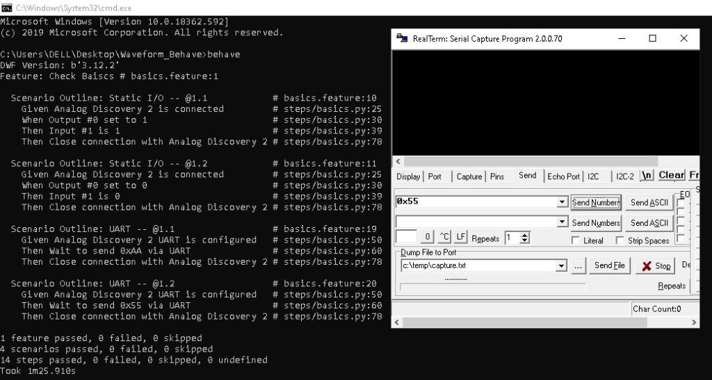
To run the feature file, we will run behave command inside the directory. This is how the testing will look like when it passes every thing.

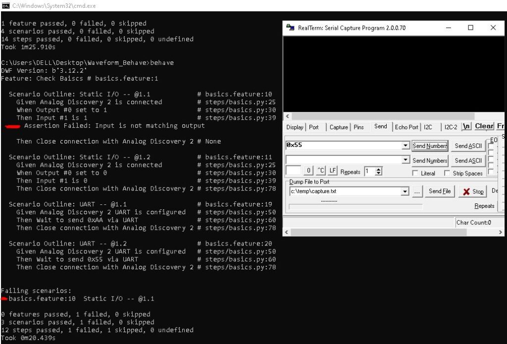
Let’s do an intentional error, by removing the connection between the output pin and the input pin and run again the file.

That was a quick overview of using Analog Discovery 2 as a testing platform to perform the testing plans. Do you usually use a better way to do Hardware test plans? Please share your thoughts in a comment.
Read more about Analog Discovery 2:
- The Multi-function Instrument “Analog Discovery 2” Review
- ‘Given’ Hardware Behavioral Testing Is Needed ‘Then’ Use Analog Discovery 2 With Behave Python Framework
- Use AD2 to Check FT2232H Outputs


