It has been more than one year when I ordered a clone of Saleae USB Logic Analyzer from Aliexpress for about $6. The cheapest original one costs more than $100. I know this should be the cost of development, and these cloning techniques is bad for companies that make their living from selling the hardware, but this is life (sorry Saleae team).
I always planned to try it, and this week I had the time for that. I would like to share with you a quick overview of this tool.
The Hardware
The package of Saleae Analyzer Clone contained the analyzer itself, a USB Cable and 10 Jumper Wires female-female.

The PCB inside the enclosure looks like this:
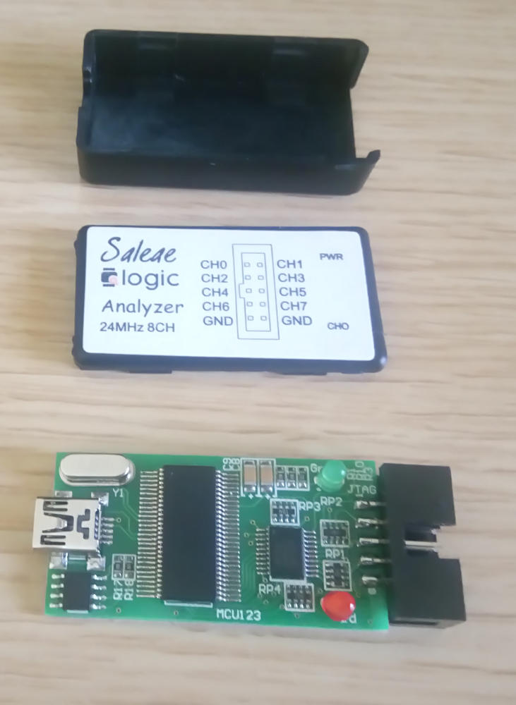
The PCB is very simple. It contains:
- CY7C68013A: A Microcontroller from Cypress with USB interface and 8051 microprocessor core.
- AT24C01B: A 128 Byte serial EEPROM from ATMEL.
- 74HC245: An Octal bus transceiver.


I always find it nice to understand some of the undergoing process behind the tool-chain of hardware and software. Firstly, you must know that CYC68013A MCU doesn’t have a Flash (non-volatile) memory, instead, the code is loaded into the internal RAM via USB or the EEPROM and while the EEPROM is 128 Byte, I was sure that the code is loaded from the USB. So the first interesting fact is that I basically bought only the PCB with no firmware inside. Secondly and apparently, the EEPROM contains some information related to the device as a USB device (VID, PID, .. etc). This information is important to make the clone tool look like the original one for the software tool (I mean the tool from Saleae). Here is an example output of lsusb -v command using Linux machine with the clone attached.
Bus 001 Device 032: ID 0925:3881 Lakeview Research Saleae Logic
Device Descriptor:
  bLength                18
  bDescriptorType         1
  bcdUSB               2.00
  bDeviceClass          255 Vendor Specific Class
  bDeviceSubClass       255 Vendor Specific Subclass
  bDeviceProtocol       255 Vendor Specific Protocol
  bMaxPacketSize0        64
  idVendor           0x0925 Lakeview Research
  idProduct          0x3881 Saleae Logic
Thirdly, the Octal bus transceiver is to protect (I think) the “3.3-V operation with 5-V tolerant” inputs, where the inputs of the transceivers have clamping diodes.
You may find other clones. I’ve found a slightly different one in this article. In the same article, the writer introduces how to reach and change the EEPROM content without de-soldering it.
I should say by the end of this paragraph that maybe if I knew the first fact before buying this tool, I think I would buy a same function breakout board like this one!
Test Use Case
Just for the test, I will try to sniff the RX/TX lines of ESP8266 while uploading a firmware using Bootloader.

Although the sniff can be done using some software sniffing tools, this is not my case.
The Software
sigrok Tool
A long time ago, I’ve heard about an open-source tool called sigrok and I wanted to give it a try. According to sigrok official definition it’s a project aims at creating a portable, cross-platform, Free/Libre/Open-Source signal analysis software suite that supports various device types
This tool is cross-platform, so choose what fits you. The most important parts of this project are (as a normal user):
- sigrok-cli : The command-line client for the sigrok software.
- PulseView : a Qt-based GUI for sigrok.
- fx2lafw : an open-source firmware for Cypress FX2 (CY7C68013A uses FX2) that makes them usable as simple logic analyzer and/or oscilloscope.
Note: fxlafw will not be testing in this micro-blog, but Markus Zenspammer in the comments section mentioned fx2lafw and seems he tested it successfully.
After you download the tools and before running them, you should get the right firmware for this Saleae logic analyzer. As most firmware files are non-free and sigrok team don’t have the permission to (re-)distribute them. So you need to add it to the installed package manually. In our case, first, you need to download Saleae Logic official tool, then download the script files here. Now, put these scripts in the same directory of Logic tool and execute sigrok-fwextract-saleae-logic16 python script. The script will extract (from the “Logic” binary) the FX2 firmware. Finally, you need to move the output files to /sigrok-firmware directory (it’s /usr/share/sigrok-firmware on my machine). Here is an example of the process:
$ sigrok-fwextract-saleae-logic16 Logic
saved 5214 bytes to saleae-logic16-fx2.fw
saved 149516 bytes to saleae-logic16-fpga-18.bitstream
saved 149516 bytes to saleae-logic16-fpga-33.bitstream
Now you can run PulseView and connect to the analyzer.

If you’re a bit curious like me, you can enable debug output messages from PulseView (pulseview -l 5) to see what’s happening in the background. This is an interesting debugging information.
sr: fx2lafw: fx2lafw: Closing device 0 on 1.26 interface 0.
sr: ezusb: uploading firmware to device on 1.33
sr: ezusb: setting CPU reset mode on...
sr: ezusb: Uploading firmware at /usr/share/sigrok-firmware/fx2lafw-saleae-logic.fw
sr: ezusb: Uploaded 4096 bytes
sr: ezusb: Uploaded 4024 bytes
sr: ezusb: Firmware upload done
Using PulseView is very straightforward; first you need to configure the frequency of sampling and the size, also you have 8 channels displayed and you can rename it from the numeric value to any meaningful name by clicking on the tag.

The last important cornerstone feature is the protocol decoder. You can add it from (decoders>add>UART). To configure the decoder you need to click on the decoder name tag shown in the margin. If you like to measure time exactly you can use the cursors (view>Show Cursors).
Note: Increase the samples size when you increase the sample rate. When I choose less than 1G samples with 1MHz rate the tool won’t run.
Saleae Logic
It’s the official software tool for Saleae’s products. The cloned version works well using it. I should admit, this tool is more user-friendly and has more features than sigrok tool. You can find a nice guide in Saleae’s website.

Last, try to read Markus Zenspammer handy comparison between Saleae and Sigrok project in the comments section.