
All About ESP32 Parts
- Part 1: Overview, Tools and blinking LED
- Part 2: Logging and WiFi Basics
- Part 3: TCP and HTTP via WiFi
- Part 4: Bluetooth Low Energy (BLE) Basics
Related Articles
ESP32 is a very rich SoC with a lot of peripherals, where the datasheet counts 19 peripherals beside the WiFi and Bluetooth ones. Not only that; ESP32 has (specific versions) dual core 32-bit microprocessor. And that’s why this series is named “All About ESP32”, because ESP32 has a lot of features to be discovered.
Overview
Ordering ESP32
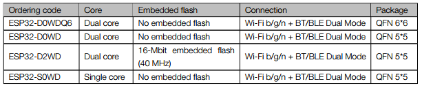
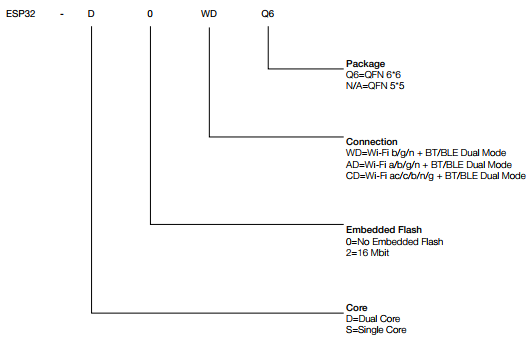
ESP32 versions has a several variations based on:
- The number of cores.
- The existence of internal 16-Mbit flash memory inside the chip.
- The size of the package.
Expressif provides ready-to-use modules with internal ESP32 IC connected with all other needed discrete components, flash memory, SRAM memory (for some modules) and PCB Antenna (for some) to make the bare ESP32 IC works. However, for reference, you can check Expressif modules official page.
| Module Name | ESP32 Version | External Memories | Antenna(s) |
|---|---|---|---|
ESP32-WROOM-32 | ESP32-D0WD | 4-MB flash memory | PCB antenna |
ESP32-WROOM-32D | ESP32-D0WD | 4-MB flash memory | PCB antenna |
ESP32-WROOM-32U | ESP32-D0WD | 4-MB flash memory | IPEX antenna |
ESP32-WROVER | ESP32-D0WD | 4-MB flash memory & 4-MB SRAM memory | PCB antenna |
ESP32-WROVER-I | ESP32-D0WD | 4-MB flash memory & 4-MB SRAM memory | PCB antenna & IPEX antenna |
ESP32-SOLO-1 | ESP32-S0WD | 4-MB flash memory | PCB antenna |
So according to this tables all available modules, except ESP32-SOLO-1 which uses the single core edition ESP32-S0WD, use the same ESP32 part number, ESP32-D0WD. The things they differ in are:
- Antenna type.
- Existence of 4 MB SRAM.
The last package of ESP32 to mention is ESP32-PICO-D4 which is a System-in-Package (SiP) module which according to Expressif integrates all peripheral components, including a crystal oscillator, flash, filter capacitors and RF matching links in a single package.

The last thing to talk about ordering ESP32 is the development boards. Today, development boards are countless to talk about. You can get one of the official Dev KITS from Expressif, or get one from well known vendors like SparkFun ESP32 Thing or purchase one of the low cost Chinese boards like the one I have right now Goouuu-ESP32 Development Board.

Key Features
ESP32 provides 2 Wireless connectivity options; a WiFi transceiver unit that supports 802.11 b/g/n and a Bluetooth v4.2 unit. The CPU and available embedded memories are key features for any MCU. As declared in the previous section ESP32 has Xtensa single-/dual-core 32-bit LX6 microprocessor(s) with internal 448 kB ROM and 520 kB SRAM with support to connect up to 4 x 16 MB flash/SRAM via QSPI interface. ESP32 has Caches, MPU and MMU to manage on-chip memories, off-chip memories, and peripherals access.
This Swiss Army Knife not only has Peripherals, but also embedded sensors:
- -40°C to 125°C temperature sensor.
- 10 capacitive-sensing GPIOs (touch sensor).
- A Hall sensor, thus for instance with a magnetic and ESP32 magnetic field-sensing, we can build a simple door status application.
To count “some” of the available peripherals :
- 34 GPIO pins.
- 18 channels 12-bit SAR ADCs.
- Two 8-bit DAC channels
- Ethernet MAC Interface
- SD/SDIO/MMC host controller
- SDIO/SPI Slave Controller
- Three UART interfaces
- Two I2C bus interfaces
- Two standard I2S interfaces
- Eight channels of infrared remote transmission and receiving
- Pulse Counter
- Hardware accelerators
- Pulse Width Modulation (PWM)
- DMA Controller
- Two timer groups, including 2 x 64-bit timers
The designers of ESP32 brought a good attention for Low Power Management which included adding a complete ultra-low-power processor called ULP co-processor with 8 KB of SRAM for instructions and data. This co-processor has its own architecture, binary file and toolchain, check the ESP-IDF programming guide for more information.
Software Tools / Toolchain
Like ESP32’s ancestor ESP8266, there are two common options to deal with ESP32: to use the official SDK from espressif or to use Arduino core for ESP32. Although these are not real independent options, because basically Arduino core just uses ESP32 SDK from espressif. It’s just an abstraction level.
For many reasons, including better performance, trouble-free and more in depth understanding, this series will use the ESP32 SDK. not like ESP32’s ancestor ESP8266, there is no non-os SDK option. ESP-IDF (Espressif IoT Development Framework) (AKA SDK) uses FreeRTOS . Of course, too many option are still there like using Javascript or python to write the code; ESP32’s page on Wikipedia has a good list about them.
There isn’t any benefit to rewrite about configuring and downloading the toolchain which is documented very well at ESP-IDF Programming Guide. Let’s say you have downloaded and configured successfully the toolchain and ESP-IDF on you machine. As a checklist you need to have:
- The toolchain.
- ESP-IDF from ESP-IDF repository.
After a successful configuration, the following outputs should appears using the following commands via Linux terminal or MinGW for Windows:
- Command: echo $IDF_PATH
Output: \your\path\to\esp-idf - Command: printenv PATH
Output: /home/user-name/esp/xtensa-esp32-elf/bin
Blink LED Demo
To take a ready template of ESP-IDF project we will copy one of the examples available in the original ESP-IDF to the workspace directory.
mkdir esp32-workspace

cp -r $IDF_PATH/examples/get-started/hello_world esp32-workspace/first_app
This command will copy “hello_world” folder to “first_app” folder in the “esp32-workspace”.
Before finding out how to build the source file and flash to ESP, let’s write and understand the code first.
Header files section
#include "freertos/FreeRTOS.h"

#include "freertos/task.h"
These two header files are needed as the code will uses an API from FreeRTOS, beside the following header file which contains the prototype for the API function being used to deal with the GPIO.
#include "driver/gpio.h"
app_main function
This is the main function which contains the actual program. As the IDF uses FreeRTOS, then we can create a task to do the blinking thing. Task creation in FreeRTOS is done by calling xTaskCreate function. You may be not familiar with FreeRTOS, thus every time something is needed from FreeRTOS, it will be explained. Let’s start with xTaskCreate; it has the following declaration, and the following is quoted from FreeRTOS reference manual :
BaseType_t xTaskCreate( TaskFunction_t pvTaskCode,
const char * const pcName,
unsigned short usStackDepth,
void *pvParameters,
UBaseType_t uxPriority,
TaskHandle_t *pxCreatedTask );
This function creates a new instance of a task, and takes the following parameters:
- pvTaskCode: Tasks are simply C functions that never exit and, as such, are normally implemented as an infinite loop. The pvTaskCode parameter is simply a pointer to the function (in effect, just the function name) that implements the task.
- pcName: A descriptive name for the task. This is mainly used to facilitate debugging, but can also be used in a call to xTaskGetHandle() to obtain a task handle.
- usStackDepth: Each task has its own unique stack that is allocated by the kernel to the task when the task is created. The usStackDepth value tells the kernel how large to make the stack.
- pvParameters: Task functions accept a parameter of type ‘pointer to void’ ( void* ). The value assigned to pvParameters will be the value passed into the task.
- uxPriority: Defines the priority at which the task will execute. Priorities can be assigned from 0, which is the lowest priority, to (configMAX_PRIORITIES – 1), which is the highest priority.
- pxCreatedTask: pxCreatedTask can be used to pass out a handle to the task being created.
According to the description, the following is a call to xTaskCreate API to create “blink_task”:
xTaskCreate(&blink_task, "blink_task", configMINIMAL_STACK_SIZE, NULL, 5, NULL);
blink_task Function
void blink_task(void *pvParameter)

{
    gpio_pad_select_gpio(BLINK_GPIO);

    gpio_set_direction(BLINK_GPIO, GPIO_MODE_OUTPUT);

    while(1) {
       gpio_set_level(BLINK_GPIO, 0);

       vTaskDelay(1000 / portTICK_PERIOD_MS);
       gpio_set_level(BLINK_GPIO, 1);
       vTaskDelay(1000 / portTICK_PERIOD_MS);
    }
}
The code of blink_task function is straight forward, like any other GPIO code, it includes: selecting the pin function, set GPIO pin mode and set the level, and all of these functions are from ESP-IDF.
Now, let’s see what is vTaskDelay(), and I will quote from FreeRTOS reference manual : “vTaskDelay Places the task that calls vTaskDelay() into the Blocked state for a fixed number of tick interrupts”. portTICK_PERIOD_MS is macro for the period of each tick in mS, so for 1000mS delay, we need 1000/portTICK_PERIOD_MS of ticks.
Now let’s see the full code:
#include "freertos/FreeRTOS.h"
#include "freertos/task.h"
#include "driver/gpio.h"

#define BLINK_GPIO 1

void blink_task(void *pvParameter)
{
    gpio_pad_select_gpio(BLINK_GPIO);

    gpio_set_direction(BLINK_GPIO, GPIO_MODE_OUTPUT);

    while(1) {

       gpio_set_level(BLINK_GPIO, 0);

       vTaskDelay(1000 / portTICK_PERIOD_MS);

       gpio_set_level(BLINK_GPIO, 1);

       vTaskDelay(1000 / portTICK_PERIOD_MS);

    }
}

void app_main()
{
    xTaskCreate(&blink_task, "blink_task", configMINIMAL_STACK_SIZE, NULL, 5, NULL);
}
Building The Code
The previous code should be in first_app/main/first_app_main.c, and the terminal should be pointing to the the first_app directory. Running make command will display a simple GUI:

This menu has a lot of options which we will discover later but what we should concern about is choosing the right Serial port for the ESP32 board to be used when flashing. You can save the configuration so the next time you use make command, the toolchain will do the work directly with the saved configuration. This process is shown in the following record:

Another option is to use “make flash” command which will build the source files and flash it. To enforce the menu to appear again “make menuconfig” should be used.
A successful flashing should prints on the terminal something like this:

Read More
That’s all for now, see you in the next part.
Meanwhile, I would advise all readers to have a look at “Kolban’s Book on ESP32”. As he mentions in the introduction “this is not exactly a book but a notebook rather, where the paragraphs are scattered and need some rearrangement (until the time of writing these words)”, but it’s really worth to read his worthy notes about almost anything related to ESP32 and the concepts related to it. Another strongly suggested resource is LUCA’s series about ESP32 he talked about a lot of topics related to ESP32 in an amazing way that cares about details. Lastly and mostly, the official documentation.
All About ESP32 Parts
- Part 1: Overview, Tools and blinking LED
- Part 2: Logging and WiFi Basics
- Part 3: TCP and HTTP via WiFi
- Part 4: Bluetooth Low Energy (BLE) Basics
Related Articles
Great tutorial have been looking for IDF tutorial that explains the code. Could you please do a tutorial on the GPIO interrupts.