Because of its easy use and low cost, Arduino boards succeed to spread to a variety of applications, especially in robotics and electronic devices. But can this board alone be used to construct a robot that is able to navigate autonomously and plot a 2D map? The answer simply is NO!
The most recognized Arduino boards like UNO or MEGA have AVR internal Micro-controllers with processing potentials that aren’t suitable for such complicated applications or image processing.
So, can Arduino be used in high-level applications? Yes, it can be used in some aspects of these applications, for example, connecting robot’s sensors and motors to a more advanced computer – PC or Raspberry SBC – that will run the actual processing.
Since ROS is used with complex robot applications, we can dedicate it to the image processing task and use Arduino to get sensors’ readings. Now the question is how to communicate these sampled reading to our ROS?
What is rosserial?
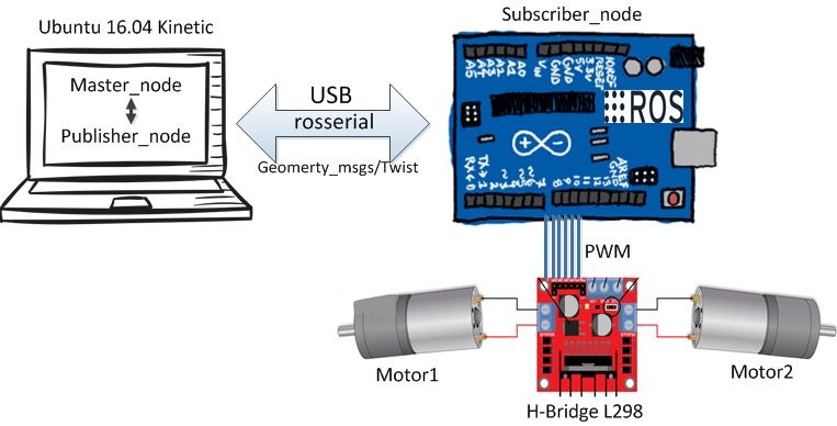
This information is communicated with the help of the rosserial package. rosserial is a protocol to send data through a serial interface. In a client-server rosserial implementation, a rosserial-server is a computer running ROS and a rosserial-client is the microprocessor that receives sensors’ data and transports it to the server in the form of ROS messages. rosserial-server in this implementation is a publishing node while rosserial-client is a subscriber node, although this can sometimes be the other way round.
Rosserial-client package is available for several microprocessor types including Arduino, STM32, embeddedlinux and others. While rosserial-server package is available in Python or C++ versions.

Image courtesy ROS Integration for Miniature Mobile Robots
This article will go through the setup of Arduino and rosserial.
Installing rosserial package on Ubuntu
There are two methods to install any package on Ubuntu:
- Using apt-get
To install rosserial on ROS kinetic, type
sudo apt-get install ros-kinectic-rosserial
- Source code clone
First, create a new folder in your ROS workspace and name it rosseiral_ws for example. Create another folder inside named src
mkdir -p ~/rosserial_ws/src
Move to your src folder
cd ~/rosserial_ws/src
Clone the source code in this directory
git clone https://github.com/ros-drivers/rosserial.git
When the clone is complete, we need to build the package in the workspace. Go back to the main folder
cd ~/rosserial_ws
Then type this command. It will build the package creating build and devel folders
catkin_make
To introduce the installed package to ROS, use the following
source ~/rosserial_ws/devel/setup.bash
Setup ros_lib into Arduino IDE
For Arduino to be able to communicate with ROS, ros_lib must be installed. The next steps will guide you through this.
In your Arduino environment go to file-> preferences. For sketchbook location, look for libraries folder -create it yourself in case you can’t find it –

- Now, in the command window, type
cd sketchbook/libraries
roscore
- In a new window, use rosrun command to generate ros_lib
rosrun rosserial_arduino make_library.py
You can see ros_lib included in your custom libraries list

Example 1: Blinking LED
This is the most basic example application. The following code sets up a node that subscribes to a topic that changes the state of a LED connected to pin 13. This code can be found in ros_lib -> Blink
#include <ros.h>
#include <std_msgs/Empty.h>

ros::NodeHandle nh;
void messageCb( const std_msgs::Empty& toggle_msg){
  digitalWrite(13, HIGH-digitalRead(13));
}
ros::Subscriber<std_msgs::Empty> sub(“toggle _led”, &messageCb );
void setup()
{
  pinMode(13, OUTPUT);
  nh.initNode();
  nh.subscribe(sub);
}
void loop()
{
  nh.spinOnce();
  delay(1);
}
Let’s explain the code:
#include <ros.h>
includes ROS library in the program
#include <std_msgs/Empty.h>
includes the messaging library that manages communication between publishers and subscribers. Since this application doesn’t need to exchange real data, an empty message is used and the code only creates a subscriber and no publisher gets created.
The operation is illustrated as

ros::NodeHandle nh
makes this program as a node in ROS . It’s a node object.
void messageCb( const std_msgs::Empty& toggle_msg){
digitalWrite(13, HIGH-digitalRead(13));
}
Define the method that will be called when the topic message is received. When this method is called, the value on pin 13 is toggled.
ros::Subscriber<std_msgs::Empty> sub(“toggle _led”, &messageCb )
Creates a subscriber to the “toggle_led” topic with the callback function “messageCb” to be called on receiving a message.
pinMode(13, OUTPUT)
defines pin 13 as output
nh.initNode()
init the node
nh.spinOnce()
checks if there are any callbacks/services to control the update rate of ROS.
nh.subscribe(sub)
subscribe/start listening
To run the code, open cmd window and type
roscore
To run rosserial client that passes the messages from Arduino to ROS
rosrun rosserial_python serial_node.py /dev/ttyUSB0
Before uploading your code, check which port your Arduino is attached to by going to tools->port, or by using dmesg command

To turn on the LED
rostopic pub toggle_led std_msgs/Empty –once
Now you can see the LED blinking

The following code is used as a template to write your custom publisher
#include <ros.h>
ros::NodeHandle nh;

std_msgs::String str_msg;
ros::Publisher pub("any_topic", &str_msg);

void setup(){
...
nh.advertise(pub);
...
}

void loop()
{
pub.publish( &str_msg );
nh.spinOnce();
}
In general, you need to do these steps:
- Include ROS lib
- Create a node to communicate with ROS
- Create a publishing node: the first parameter is the topic’s name and the second is the callback function.
- Start this publisher
Example 2: Motor Controller
This application is a little more complicated. Let’s assume a two-wheeled robot needs to be controlled using ROS. In terms of hardware, we need:
- Arduino board
- Motor driver
- DC motors
L298 is used for driving the motors. It contains two H-bridge circuits, which has four input pins to enable the transistors and the motor is connected between the two output pins out1 and out2. This figure shows the internal structure of L298

H-bridge controls the voltage polarity. Therefore, if the goal is to control the rotation direction all you need to do is control which transistor to enable. For example, enable transistors 1&4 to rotate clockwise. While enabling 2&3 will produce anti-clockwise rotation.

We will connect 1 and 2 to Arduino pins and Out1 to one motor. Also, 3 and 4 to Arduino pins and Out2 to the other motor. The goal here is to control the speed of the motors, thus, the input voltage needs to be controlled using a Pulse Width Modulation (PWM). PWM values are between 0 and 225 while motors duty values are between 0% and 100%. As an example, to rotate in full duty, PWM=255. And to stop rotating PWM=0
In ROS there is a twist message in geometry_msgs package called cmd_vel which we can make use of to send speed values to the motors.
The next block diagram illustrates the idea

//Code Authors:
//* Ahmed A. Radwan (author)
//* Maisa Jazba

#include <ArduinoHardware.h>
#include <ros.h>
#include <geometry_msgs/Twist.h>


#define EN_L 9
#define IN1_L 10
#define IN2_L 11

#define EN_R 8
#define IN1_R 12
#define IN2_R 13


double w_r=0, w_l=0;

//wheel_rad is the wheel radius ,wheel_sep is
double wheel_rad = 0.0325, wheel_sep = 0.295;


ros::NodeHandle nh;
int lowSpeed = 200;
int highSpeed = 50;
double speed_ang=0, speed_lin=0;

void messageCb( const geometry_msgs::Twist& msg){
  speed_ang = msg.angular.z;
  speed_lin = msg.linear.x;
  w_r = (speed_lin/wheel_rad) + ((speed_ang*wheel_sep)/(2.0*wheel_rad));
  w_l = (speed_lin/wheel_rad) - ((speed_ang*wheel_sep)/(2.0*wheel_rad));
}


ros::Subscriber<geometry_msgs::Twist> sub("cmd_vel", &messageCb );
void Motors_init();
void MotorL(int Pulse_Width1);
void MotorR(int Pulse_Width2);

void setup(){

 Motors_init();

 nh.initNode();

 nh.subscribe(sub);

}


void loop(){
 MotorL(w_l*10);

 MotorR(w_r*10);

 nh.spinOnce();

}


void Motors_init(){

 pinMode(EN_L, OUTPUT);

 pinMode(EN_R, OUTPUT);

 pinMode(IN1_L, OUTPUT);

 pinMode(IN2_L, OUTPUT);

 pinMode(IN1_R, OUTPUT);

 pinMode(IN2_R, OUTPUT);

 digitalWrite(EN_L, LOW);

 digitalWrite(EN_R, LOW);

 digitalWrite(IN1_L, LOW);

 digitalWrite(IN2_L, LOW);

 digitalWrite(IN1_R, LOW);

 digitalWrite(IN2_R, LOW);

}

void MotorL(int Pulse_Width1){
 if (Pulse_Width1 > 0){

     analogWrite(EN_L, Pulse_Width1);

     digitalWrite(IN1_L, HIGH);

     digitalWrite(IN2_L, LOW);

 }

 if (Pulse_Width1 < 0){

     Pulse_Width1=abs(Pulse_Width1);

     analogWrite(EN_L, Pulse_Width1);

     digitalWrite(IN1_L, LOW);

     digitalWrite(IN2_L, HIGH);

 }

 if (Pulse_Width1 == 0){

     analogWrite(EN_L, Pulse_Width1);

     digitalWrite(IN1_L, LOW);

     digitalWrite(IN2_L, LOW);

 }

}


void MotorR(int Pulse_Width2){


 if (Pulse_Width2 > 0){

     analogWrite(EN_R, Pulse_Width2);

     digitalWrite(IN1_R, LOW);

     digitalWrite(IN2_R, HIGH);

 }

 if (Pulse_Width2 < 0){

     Pulse_Width2=abs(Pulse_Width2);

     analogWrite(EN_R, Pulse_Width2);

     digitalWrite(IN1_R, HIGH);

     digitalWrite(IN2_R, LOW);

 }

 if (Pulse_Width2 == 0){

     analogWrite(EN_R, Pulse_Width2);

     digitalWrite(IN1_R, LOW);

     digitalWrite(IN2_R, LOW);

 }

}
Once the code is uploaded to Arduino, the robot can be controlled using the ROS via teleop_twist_keyboard package that enables the ROS to control the linear velocity (forward and backwards) in addition to angular velocity on the z-axis. The Twist messages via cmd_vel topic are used.
Type
rosrun teleop_twist_keyboard teleop_twist_keyboard.py
This output is produced

u: for left circle
i: forward
o: right circle
j: turn anti-clockwise
K: stop all motors
l: turn clockwise
m: left circle backwards
,: straight backwards
.: right circle backwards
This article presented why it is important to connect Arduino with a ROS system. We demonstrated how to setup Arduino and Ubuntu for this connection using the rosserial protocol and ros_lib library. We then showed a simple blinking LED example and a slightly advanced one of a moving two-wheeled robot. You can check also our other tutorial about IMU sensor connected with Arduino and ROS.


In the whole Universe there isn’t such a thing like “Arduino chips”; those things don’t exist. Somebody took a nice microcontroller from Atmel and then created the Arduino platform. And as a matter of fact, the “Arduino language” doesn’t exist either. The arduinos are programmed in C++.
Please don’t invent things that mislead the people that is new in this topic.
Hi Xavier
This is Yahya from Atadiat authors team. Yes you’re totally correct. Using the word “Arduino chips” is totally incorrect and was wrongly translated from the original text. About the “Arduino language”, you’re also right but it’s very common to say Arduino-C (AKA language) while I personally avoid using this misleading term.
Please check our article “A Tour Inside Arduino Core” … to know that we don’t deal with Arduino as dummies.
https://atadiat.com/en/e-arduino-core-source-files-make-new-core-building-steps/
Thanks for your notes again.
I have managed to get it working. i forgot to use this command “rosrun rosserial_python serial_node.py /dev/ttyACM0”
Thank you very much for sharing the tutorial.
Kind regards
Nice knowledge sharing Maisa jazba.
i like your comment on simulation.
thank you.
I’m brand new to ROS, but not to building things
I’ve got 2 robots built, and I have ROS kinetic installed on one, and melodic installed on another, and I’ve been trying to find a way to install drivers for the motor controllers into ROS, but, after reading this article, I think I’ve got the whole idea wrong.
ROS doesn’t need drivers, the Arduino or Raspberry Pi does.
Tell me if I’ve got this right…
You have, in this case, an L298, connected to an Arduino, and you want to make the left motor turn at 1/2 speed forward. There is, for instance, a joystick connected to a computer running ROS Master, which publishes a msg, to which the Arduino is a subscriber.
You would then move the left joystick 1/2 forward, (which could be either digital or analogue) at which point, the ROS Master publishes a “left motor 1/2 forward”, which the Arduino receives, then sends out a 128 (1/2 of 255) signal to the L298 telling it to operate at the appropriate PWM, which makes the motor move at 1/2 speed. So the ROS has no idea what motor controller is connected to it. All ROS knows is to publish a msg saying “left motor 1/2 forward”
hi there I want to know why you multiplied w_r by 10.